Stabilizing Radial Chip Thickness in High-Efficiency Roughing
Conventional roughing toolpaths rely on linear offsets that inevitably cause catastrophic cutter overload whenever the tool encounters internal 90-degree corners. As the end mill approaches an enclosed boundary, the radial engagement angle spikes from an intentional 15 degrees up to 90 or even 180 degrees. This sudden surge in contact area generates severe heat spikes, spindle strain, and premature edge chipping.
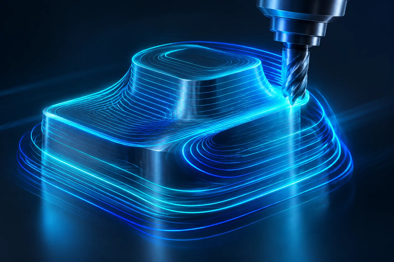
Dynamic motion toolpaths solve this mechanical failure mode by calculating continuous trochoidal arcs, variable stepovers, and micro-lift back-traverses. The CAM calculation engine adjusts the instantaneous toolpath radius so that the cutter engagement angle remains absolutely uniform throughout the entire pocket, regardless of boundary complexity or acute corner geometry.
Core Intent Rules for Dynamic Roughing
Configuring a dynamic milling cycle requires a shift in operator thinking from traditional heavy stepovers to deep axial engagement paired with light radial contact:
- Full Flute Axial Engagement: Leverage the entire flute length (1.5× to 2.5× tool diameter) to distribute abrasive wear uniformly along the carbide cutting edge rather than concentrating fatigue on the tip.
- Radial Chip Thinning Compensation: When radial stepover drops below 25% of cutter diameter, program feed per tooth must be increased proportionally to maintain the actual chip thickness required to evacuate heat effectively.
- Micro-Lift Retract Loops: During non-cutting repositioning moves, apply an axial micro-lift of 0.010 in (0.25 mm) with back feed rates up to 400 IPM to prevent bottom rubbing while keeping the machine within look-ahead acceleration limits.
By enforcing a fixed angle of engagement, cutting forces stabilize into a predictable, high-frequency shear cycle. The resulting chips absorb the bulk of the thermal energy, leaving the workpiece and cutting tool remarkably cool even when operating dry in hardened tool steels and high-temp nickel alloys.