Radial Immersion and Chip Thinning Physics
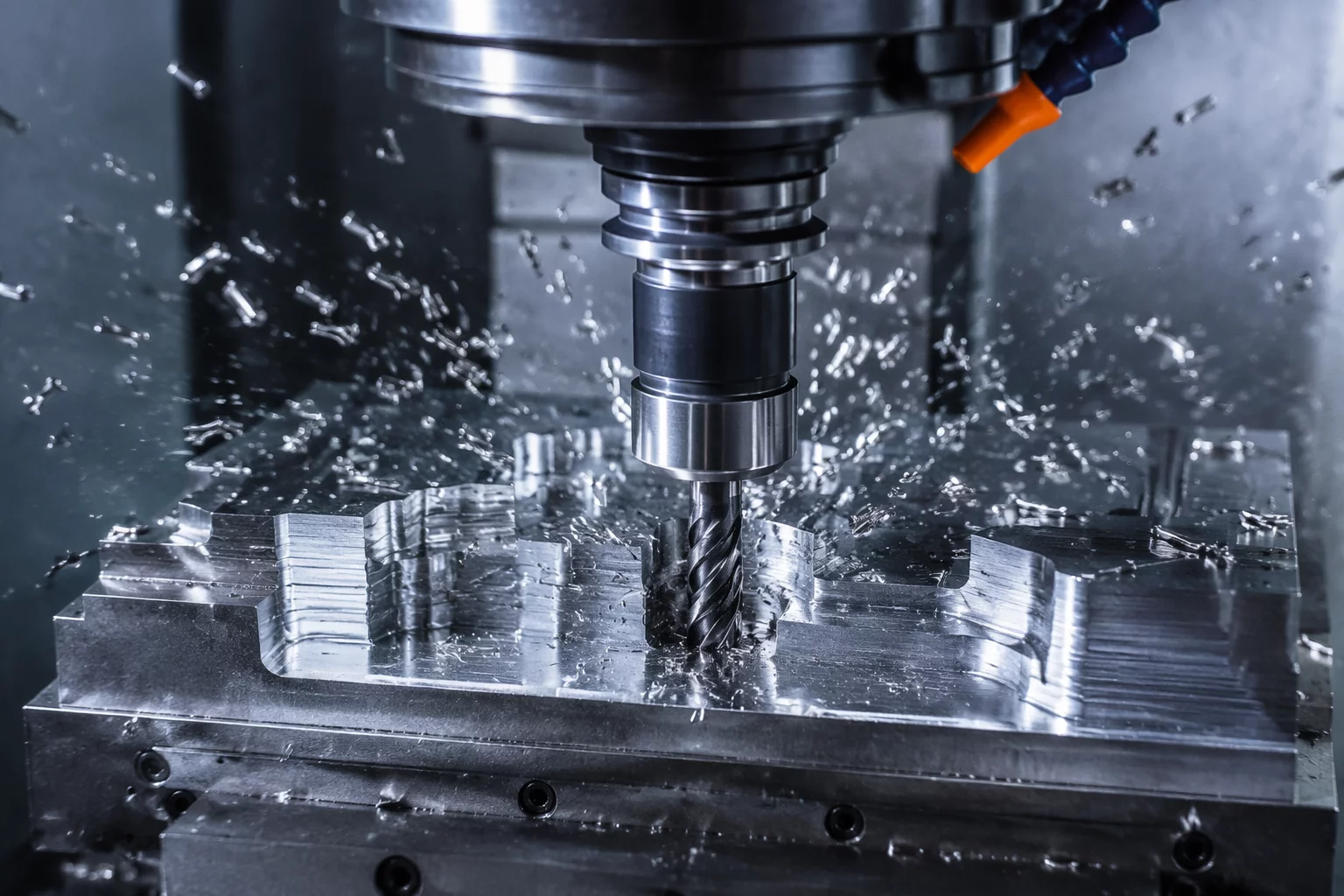
High speed roughing flips traditional milling doctrine upside down. Instead of driving an end mill deeply and slowly into raw billet material with broad radial engagement, this technique pairs light radial stepovers with deep axial passes and significantly elevated surface speeds. When radial engagement drops below twenty-five percent of the cutter diameter, the physical chip formed at the flute entrance is substantially thinner than the machine table advance per tooth. This reality—termed radial chip thinning—demands a calculated increase in feed rate to maintain the target chip thickness.
Failure to compensate for chip thinning results in tool rubbing, localized heat accumulation, and accelerated flank wear. By actively increasing feed rates to offset the thinning factor, the cutter slices through the stock with minimal thermal migration into the workpiece. The thermal energy instead evacuates almost entirely with the flying chip stream, preserving both cutter substrate integrity and workpiece metallurgical stability.
Feed Rate Regulation and Stepovers Across Geometry Shifts
Managing high speed passes requires careful synchronization between the programmed radial stepover, machine acceleration capabilities, and dynamic motion loops. In modern toolpaths like those in Mastercam 2026.R2 and Mastercam 2027, the CAM engine maintains a strictly controlled angle of engagement. When tools encounter enclosed corners or complex interior walls, they adjust automatically using trochoidal motion rather than jamming into pocket vertices.
- Calculated Stepover Limits: Keep radial width of cut between 8% and 15% of tool diameter for titanium and tool steels, expanding to 20%–25% for aerospace aluminum alloys.
- Spindle Load Equilibrium: Maintain constant cutting force through dynamic arc radius expansion, eliminating sudden current spikes in the spindle motor.
- Smooth Micro-Lifting Retracts: Utilize slight 0.25mm Z-axis lifts during rapid repositioning loops to prevent floor scuffing and friction wear.
Executing this method consistently shortens roughing cycle durations while maximizing cutter usage along its entire usable flute height. Rather than concentrating wear on the tool tip, the cut spreads across the entire flute cylinder, generating uniform step remnants that simplify subsequent semi-finishing operations.