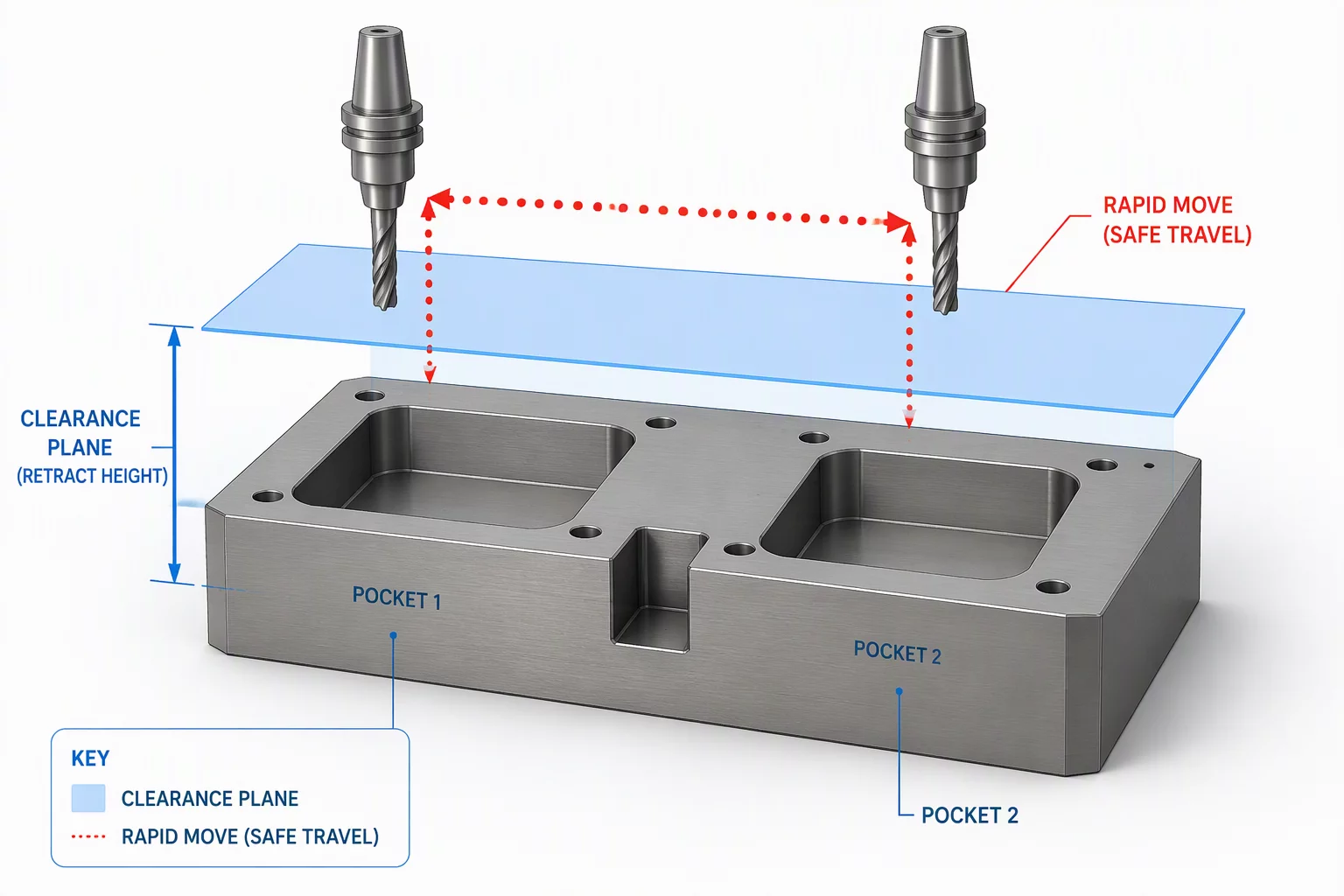
Boundary Control and Dynamic Retract Planes
Every non-cutting positioning move carries collision risk when geometric transitions cut across evolving raw stock boundaries. Establishing a single global clearance level high above clamps guarantees safety, but it routinely inflates non-cutting cycle times across complex multi-feature prisms. In high-speed milling environments, conservative full retracts waste up to twenty-five percent of overall machine cycle time on air moves.
Modern clearance architectures split the motion field into three distinct territorial zones: the absolute fixture avoidance plane, the local incremental clearance surface, and the feed-engage lead envelope. The absolute boundary protects table hardware, bolt heads, and rotary tilt brackets. The local incremental plane tracks raw material boundaries dynamically, maintaining tool proximity without crossing clamp corridors.
Systematic Plane Allocation Across Dense Geometry
When selecting clearance parameters within Mastercam 2026.R2 and Mastercam 2027 releases, programmers balance axis velocity against algorithmic trajectory complexity. Implementing layered clearance values prevents unnecessary rapid descents while keeping cutting edges clear of residual material flanks:
- Define global bounding cylinders or cylindrical clearance fields around rotary trunnion axes instead of flat Cartesian planar boundaries.
- Integrate live in-process stock models into feed-rate lead calculations, ensuring helical ramp entries initiate exactly two millimeters above actual residual stock.
- Apply high-feed retract transitions rather than unregulated G0 rapid motions when moving across shallow pocket partitions.
These structured transitions convert chaotic clearance motions into predictable, deterministic tool vectors. By treating clearance approach planes as active boundary conditions rather than static safety margins, shops protect high-precision spindle bearings while preserving aggressive cycle efficiency.