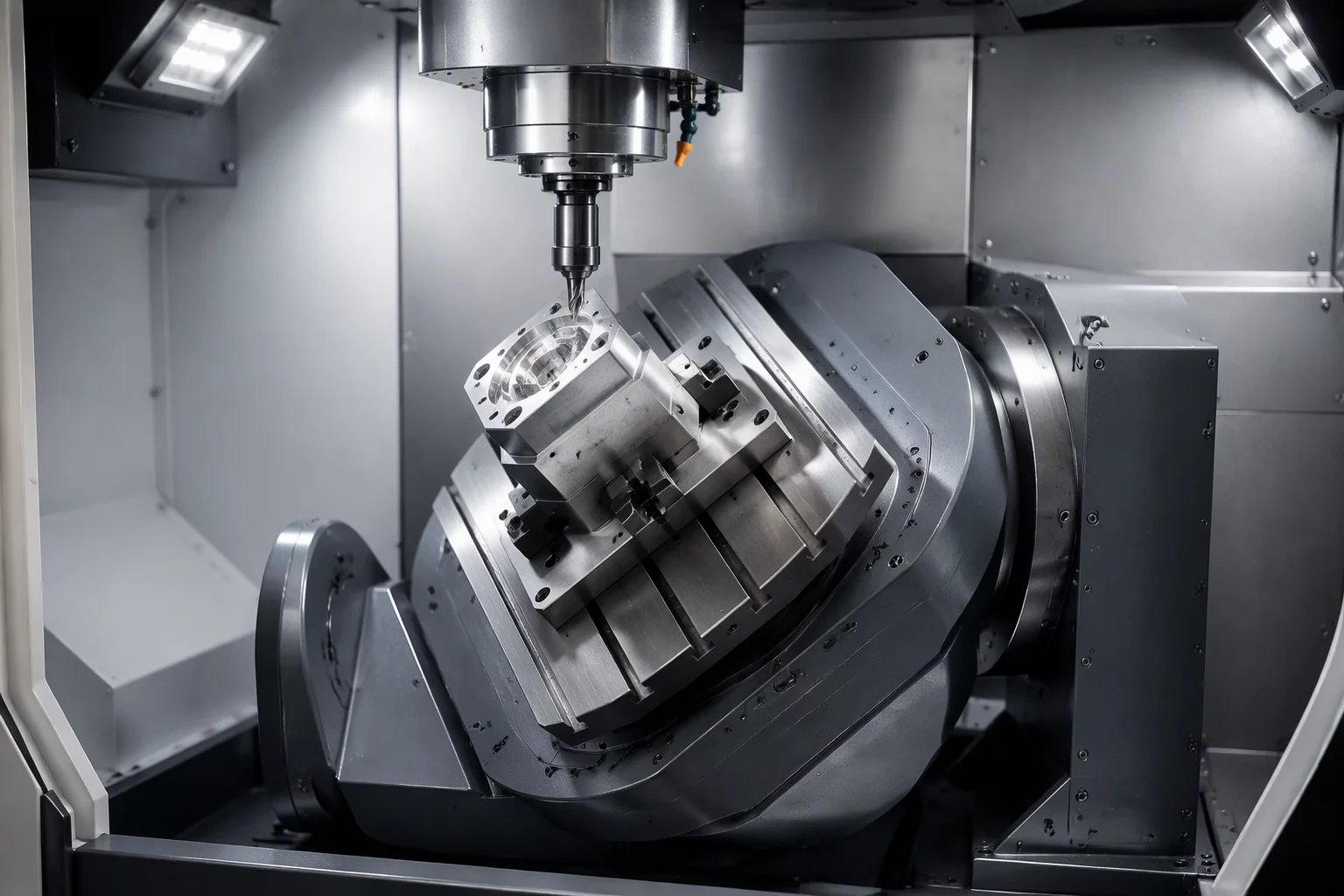
Resolving Geometric Collisions via Coordinated Tilt Control
Programming complex multi-sided prismatic parts or sculpted aerospace blisks creates an immediate dilemma between tool assembly rigidity and physical line-of-sight clearance. Programmers often extend tool stickout beyond acceptable length-to-diameter ratios just to clear surrounding flanges. This compromise causes cutting tool deflection, poor surface finishes, and accelerated insert breakdown. Multi-axis angle planning replaces excessive stickout by proactively rotating the workpiece or spindle head into the optimum cutting vector.
Inside Mastercam 2026.R2 and 2027, tool axis control strategies provide dedicated tilt planes, contact normal locks, and lead-lag vector definitions. Instead of trusting an unconstrained automated collision avoidance algorithm that swings axes erratically, programmers designate bounded angular cones. These boundary cones keep tilt changes within machine kinematics, avoiding abrupt table reversals that leave chatter marks on critical sidewalls.
Systematic Rules for Multi-Axis Tilt Configuration
Executing predictable simultaneous motion requires resolving pole singularities and managing secondary rotary travel boundaries before posting G-code to the machine:
- Enforce constant lead and tilt angles relative to surface normal vectors to preserve cutting edge sweet spots and avoid zero-velocity bottom dead center cutting.
- Maintain a 5-degree safety offset away from machine mechanical travel limits to prevent unexpected axis unwinds and emergency stops mid-cut.
- Activate interpolation-based vector smoothing across transition segments to prevent rapid rotary feed spikes and surface scalloping.
Proper angle planning balances tool holder clearances against machine dynamic limits. Running full-machine simulation with precise collet and spindle models verifies whether rotary tables can maintain target surface feed rates across tight concave pockets without stalling or violating kinematic bounds.