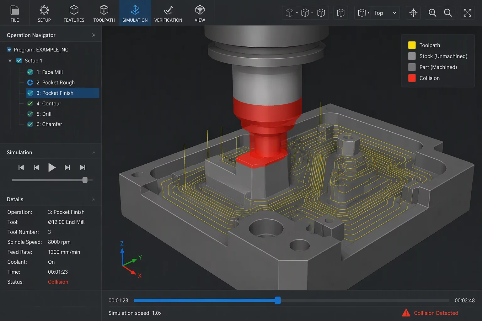
Deterministic Collision Boundary Modeling in Mastercam
Tool holder collisions remain among the most expensive mistakes on the production floor, regularly destroying carbide tooling, scrap-marking high-value raw forgings, and damaging high-speed machine spindle bearings. Relying solely on simplified cylindrical tool profiles during programming invites severe risk whenever cutters plunge near steep cavity sidewalls or fixture clamps. Modern Mastercam 2026.R2 and 2027 releases enforce accurate solid holder definition directly within the operation parameters, computing proximity checks against the active in-process stock model rather than raw design surfaces alone.
When creating high-feed milling or deep finishing routines, the CAM system dynamically computes the cross-sectional envelope of the collet chuck, shrink-fit extension, and pull stud assembly. Programmers who specify exact 3D solid step files for their tooling assemblies gain deterministic verification. The software traces every rapid plunge and feed motion against the unmachined material volume, flagging boundary violations with microscopic precision before any G-code post-processing begins.
Configuring Safety Zones and Holder Offsets
Implementing an uncompromising interference verification protocol requires establishing stratified clearance thresholds. Rather than applying a single uniform safety buffer, successful CNC machine programming separates cutter flute limits, shank relief clearance, and holder body zones into distinct protective shells:
- Radial Holder Safety Zone: Maintain a minimum radial gap of 1.50 mm to 2.50 mm between the widest collet diameter and the raw stock wall to account for material deflection and thermal spindle growth.
- Axial Gauge Length Calculation: Calculate gauge lengths precisely from the gauge line standard rather than estimated arbor projections, avoiding surprise contact along rapid lead-in ramps.
- Dynamic Multi-Axis Tilting: When clearance algorithms detect holder contact inside pockets, activate automatic collision avoidance tilt rules to re-orient the tool axis without truncating programmed toolpaths.
By synchronizing realistic holder geometry with verified stock models, programmers eliminate conservative manual air-cutting passes while fully safeguarding 5-axis and 3-axis CNC equipment from catastrophic spindle impact.