Planar Contact Dynamics and Cutter Geometry Selection
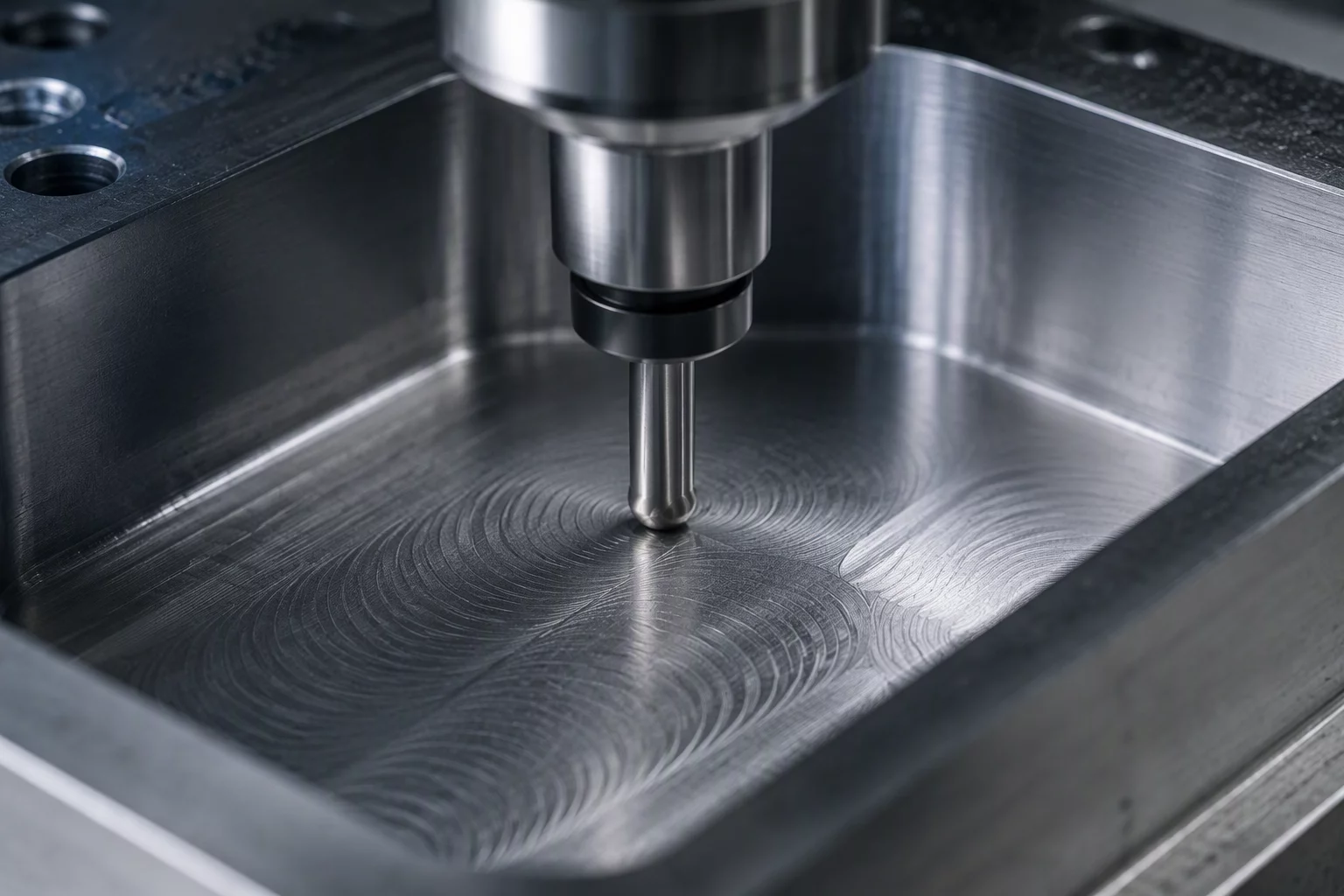
Machining expansive horizontal floors presents geometric challenges distinct from vertical wall contouring. When a flat end mill sweeps across an open pocket floor, minor spindle tram discrepancies or cutter tip deflection immediately reveal themselves through radial scarring, center dragging, and inconsistent micro-scallops. Choosing a bullnose tool with a subtle corner radius, typically 0.5 mm to 1.5 mm, shifts contact pressure inward from fragile sharp corners, distributing engagement smoothly and suppressing tool chatter during high-feed traverses.
In Mastercam 2026.R2 and Mastercam 2027, planar floor finishing routines prioritize continuous radial engagement along bidirectional sweeps. A rigid tool holding interface like shrink-fit or high-precision hydraulic chucking keeps total runout below 3 microns, preventing intermittent cutter bounce across wide surfaces. Programmers must ensure an axial stock allowance between 0.15 mm and 0.25 mm remains evenly distributed across the entire horizontal floor geometry prior to the final pass.
Mitigating Deflection, Thermal Drift, and Overlap Marks
Deflection along the Z-axis often causes shallow gouging near pocket boundaries where cutter deceleration occurs. Maintaining uniform feed rates through dynamic corner rounding softens axis turnaround spikes. To ensure surface planar integrity across high-tolerance aerospace or mold applications, apply these baseline configuration rules:
- Set radial step-over between 55% and 65% of cutter diameter to balance cycle efficiency against scallop cusp heights.
- Program tangential arc lead-in and lead-out vectors with 2 mm minimal extension to prevent dwell marks upon floor entry.
- Separate floor operations from perimeter wall passes to decouple radial wall deflection forces from vertical axial loads.
Running floor passes prior to final wall finishing avoids dragging chips against completed vertical boundaries, preserving mirror-like Ra values across the boundary seam. Utilizing climb milling across floor rasters consistently delivers predictable chip evacuation and minimizes work-hardening on alloy steels and tough titanium alloys.