Predictable Cusp Morphology and Radial Scallop Geometry
Attaining rigorous surface finish targets begins with treating scallop height as an uncompromising mathematical limit rather than a post-machining hope. On contoured surfaces, ball and bullnose cutters leave distinct cusps between adjacent step-overs. When a drawing stipulates a 32 micro-inch Ra finish, the theoretical peak-to-valley cusp must stay under 0.00012 inches, accounting for thermal expansion, runout, and tool tip deflection under cut.
In modern CAM programming like Mastercam 2026.R2 and 2027, toolpath smoothing algorithms interpolate point distribution along complex NURBS patches. A poor chordal tolerance produces faceting where flat line segments replace smooth arcs, resulting in visible witness marks and elevated Rz values. Setting chordal deviation to a strict 2:1 ratio against the line-arc filter ensures uniform motion commands, preventing the CNC control from undergoing micro-decelerations that leave burnished dwell marks.
Parametric Drivers for Micro-Inch Finish Compliance
Surface roughness is governed by cutter geometry, dynamic chip load stability, and harmonic stability across spindle engagement. Machinists often misdiagnose tool deflection marks as dull tooling, when the actual fault lies in erratic engagement angles or uneven stock left by the semi-finishing pass.
- Radial Step-over Discipline: Maintain step-over values directly coupled to corner radius geometry to ensure consistent scallop morphology across horizontal and vertical blend regions.
- Consistent Chip Thickness: Program feed rate adjustments around tight radii to avoid sudden chip load spikes that trigger cutter deflection and leave chatter bands on finish passes.
- Uniform Semi-Finish Stock: Verify that prior passes leave exactly 0.008 to 0.012 inches of stock evenly distributed, preventing tool push-off and variable depth of cut.
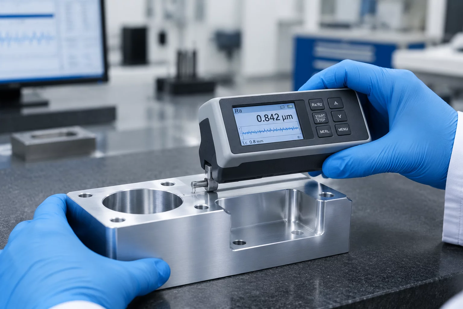
Executing finishing toolpaths with balanced mechanical loads eliminates the need for manual abrasive deburring or Scotch-Brite blending. When the cutting edge maintains uninterrupted chip shearing at constant velocity, the profilometer readings mirror theoretical CAM calculations across the entire part profile.