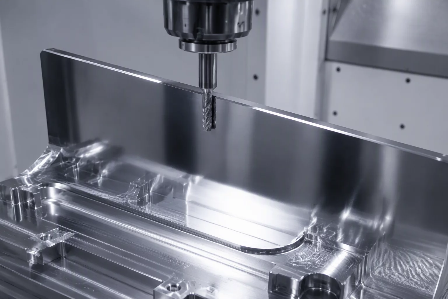
Mitigating Cutter Deflection on Vertical Boundaries
Vertical walls require a radically different CAM mindset than flat planar pockets. When a tool runs full depth along a vertical boundary, radial cutting forces push the tool tip away from the cut boundary. This displacement produces wall taper, where the top of the pocket meets dimensional tolerances while the lower portion remains noticeably thick.
Cutter deflection increases with the cube of the tool overhang length. An extended flute length doubles the mechanical leverage against the spindle taper, quadrupling the flex under identical radial engagement. Programmers frequently compensate by adjusting global lead-ins, yet the real solution sits in establishing a uniform semi-finishing radial stock offset before committing to final cleanout.
Deterministic Rules for Wall Precision
To eliminate surface rub marks and chatter scallops on tall standing ribs, implement these parameters across finishing routines:
- Stabilize radial chip thickness between 0.08 mm and 0.12 mm so the flute consistently shears rather than rubs the work surface.
- Separate finishing passes into a semi-finish step at 0.35 mm remaining stock followed by a zero-spring final contour at programmed dimensions.
- Command tangential arc roll-in entries with at least 45 degrees of swept approach to prevent dwelling witness marks at the entry point.
When working with deep internal walls exceeding a 4:1 length-to-diameter ratio, split the vertical finish into stepped axial depths with alternating climb passes. This prevents accumulated side pressure from distorting thin rib features before final floor intersections.