Establishing Deterministic Clearance Envelopes Between Distinct Cut Sequences
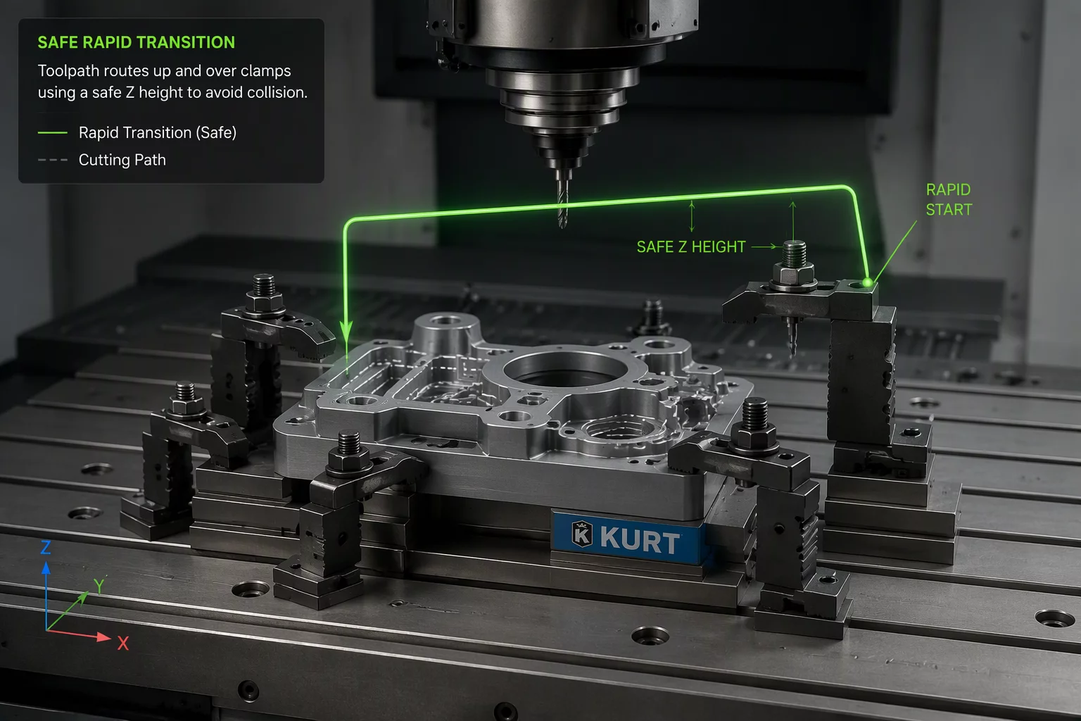
Machining operations rarely fail during heavy engagement where toolpaths receive thorough feeds-and-speeds scrutiny. Catastrophic collisions predominantly occur across the transitions between toolpaths, where cutters rapid across fixture clamps, unmachined stock islands, or complex workpiece features. Transition planning coordinates the exit vector of an active operation with the entry vector of the subsequent pass, establishing a continuous, deterministic boundary that prevents unmonitored rapid traversals through positive material.
In Mastercam 2026.R2 and 2027, safe transition planning leverages dynamic stock awareness within the linking parameter interface. By referencing the live in-process stock model rather than raw bounding envelopes, the CAM architecture automatically computes clearance planes that clear the highest physical obstacle—whether a tall modular toe clamp, an unmachined wall, or rotary trunnion elements. Transition sequences must mandate explicit retract heights that account for tool projection and holder profile geometry before any rapid axis repositioning initiates.
Core Principles for Fixture Clearance and Axis Repositioning
When repositioning cutting tools between disparate features or rotary indexing steps, the motion controller must adhere to rigid geometric safeguards. Cutting tools must never rapid on direct diagonal 3D vectors when clearing complex part envelopes. Instead, tool trajectories must separate vertical clearance motion from lateral positioning moves:
- Vertical clearance moves must achieve full clearance height above the highest workpiece or clamp feature before lateral X/Y traverse begins.
- Rotary axis unwinding and table re-indexing must strictly execute while the spindle resides at or above the designated Z-clearance plane.
- Rapid feedrates during inter-operation repositioning should utilize high-feed G01 vectors rather than uncoordinated dogleg G00 rapids.
Adhering to these transition protocols guarantees repeatable process security on multi-axis CNC machines. By decoupling vertical clearance moves from lateral table movements, programmers prevent unpredictable dogleg arc collisions. Coupled with modern stock model verification, safe transition planning eliminates expensive spindle crashes and protects critical workholding fixtures throughout multi-stage machining cycles.