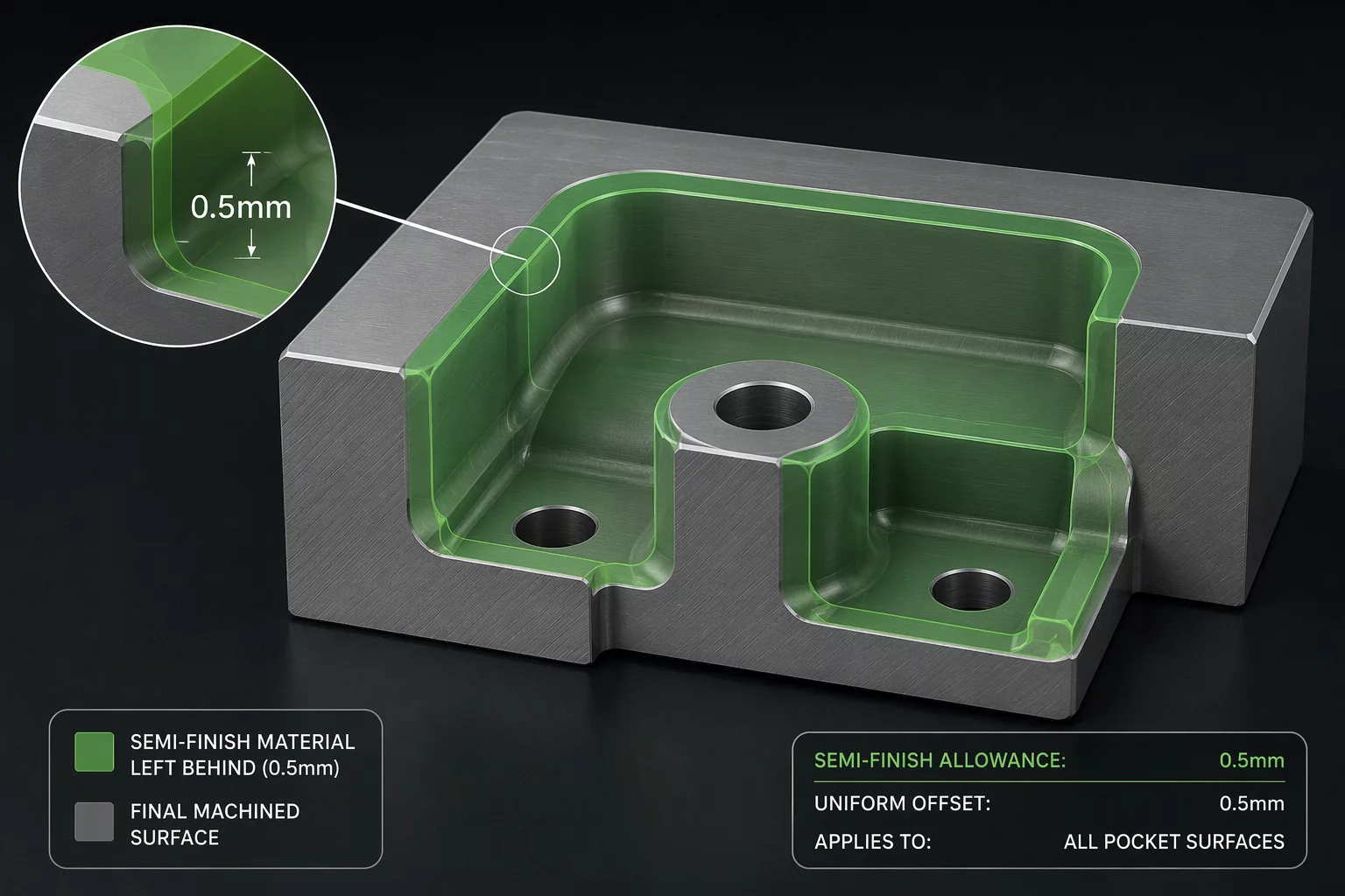
Calculating Uniform Stock Allowances for Finishing Passes
Semi-finishing serves as the vital thermal and mechanical barrier between heavy stock removal and final component accuracy. When roughing tools plow through solid stock, cutting pressures fluctuate wildly around tight pockets and steep walls. Leaving an uncontrolled roughing cusp forces the finishing cutter to absorb inconsistent chip loads, which triggers vibration, chatter marks, and accelerated tool wear. By establishing a dedicated semi-finishing phase, programmers calibrate an exact, predictable cushion across all part faces.
In high-precision aerospace and mold work, a typical semi-finishing target ranges between 0.30 mm and 0.60 mm (0.012" to 0.024") of uniform stock. This specific envelope allows the finishing tool to engage the workpiece with minimal radial deflection while still generating enough cutting resistance to prevent tool rubbing or work hardening on high-temperature alloys.
Core Principles for Managing Semi-Finish Offsets
Applying semi-finish allowances requires balancing axial steps against radial engagements. Mastercam 2026 and 2027 stock model verification tools confirm that the intermediate geometry remains smooth rather than scalloped, avoiding localized spikes in cutter force.
- Wall and floor offsets must be balanced symmetrically unless draft angles require progressive step-down passes.
- Corner radii in semi-finishing operations should remain slightly larger than the finishing tool radius to prevent sudden 90-degree corner engagement spikes.
- In-process rest models must be updated after semi-finishing to ensure finishing toolpaths do not generate air cuts or face hidden material lumps.
Adhering to these geometric boundaries guarantees that when the final finish cycle runs, the cutter experiences an identical radial width of cut across every contour. The resulting consistency eliminates wall taper, ensures sub-micron surface repeatability, and substantially prolongs carbide tool life.