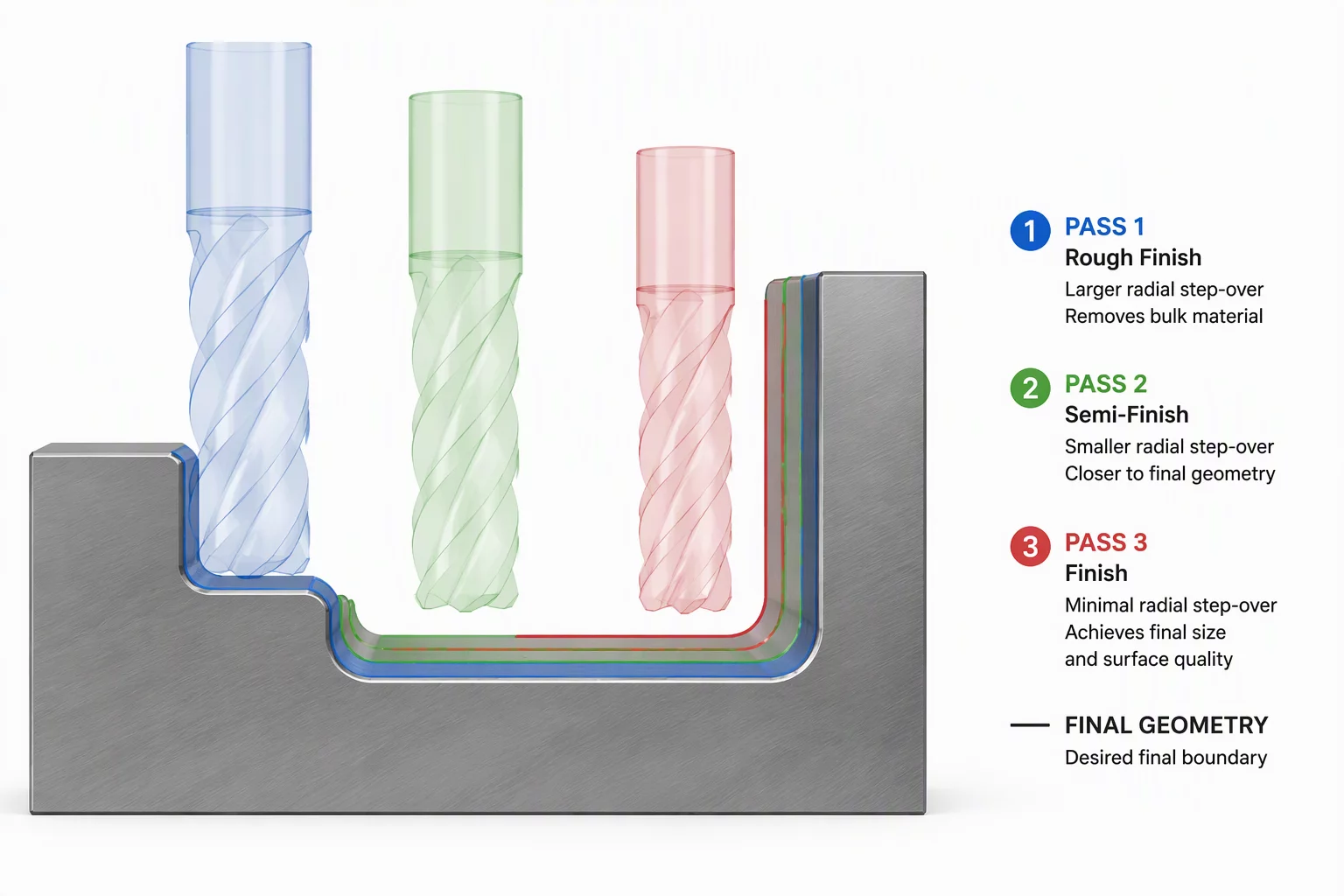
The Deterministic Role of Layered Finishing
Machining complex prismatic walls or tight mold surfaces directly from raw roughing cusps introduces severe variable cutter deflection. When a single finishing cutter contacts residual stepped stock from 2D Dynamic Mill or 3D High Speed Roughing routines, cutting pressure swings erratically between planar faces and interior corners. Dividing this final stock allowance into discrete, intentional passes isolates radial deflection completely, transforming an inconsistent cut into predictable metal removal.
In modern CAM pipelines such as Mastercam 2026.R2 and Mastercam 2027, multi-pass strategies are not redundant cycles. Programmers designate specific roles to sequential cuts: the semi-finish pass strips away bulk scallop unevenness, the primary finish pass establishes accurate geometric profile, and subsequent spring passes reclaim tool deflection without introducing thermal drift or work hardening.
Stage Breakdown: Pre-Finish, Finish, and Neutral Spring Cuts
Executing tight bore tolerances below ±0.005 mm or thin vertical webs demands strict division of radial allowances. Each pass must encounter a uniform thickness of material to sustain continuous chip thinning and prevent chatter spikes:
- Semi-Finish Pass (0.20 mm - 0.35 mm stock): Bridges roughing stair-steps and creates a uniform boundary offset, relieving high cutting forces before critical sizing begins.
- True Finish Pass (0.04 mm - 0.08 mm stock): Operates under steady-state chip load with zero chatter, generating designated surface roughness targets and blueprint dimensions.
- Neutral Spring Pass (0.00 mm programmed stock): Re-traces the final geometry at identical spindle RPM and feed rate, cleanly shaving microscopic taper left by tool push-off on long-reach tool holders.
Without this sequential segmentation, cutters flex away from the part in corners where material volume spikes, leaving positive dimensional error. Conversely, on straight open segments, the cutter straightens out, causing localized gouges. Multi-pass toolpaths establish mechanical equilibrium across the entire geometric boundary.