Toolpath Intent Architecture
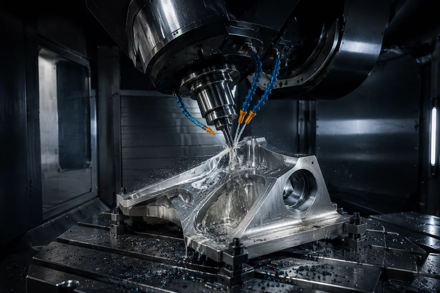
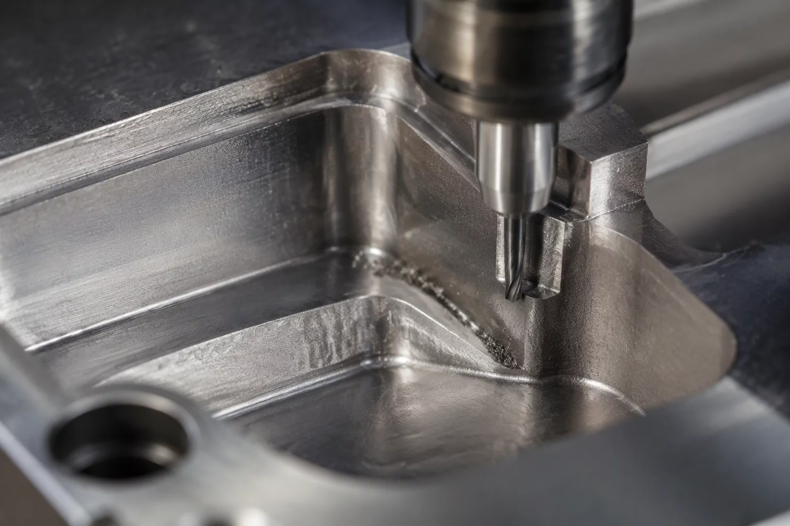
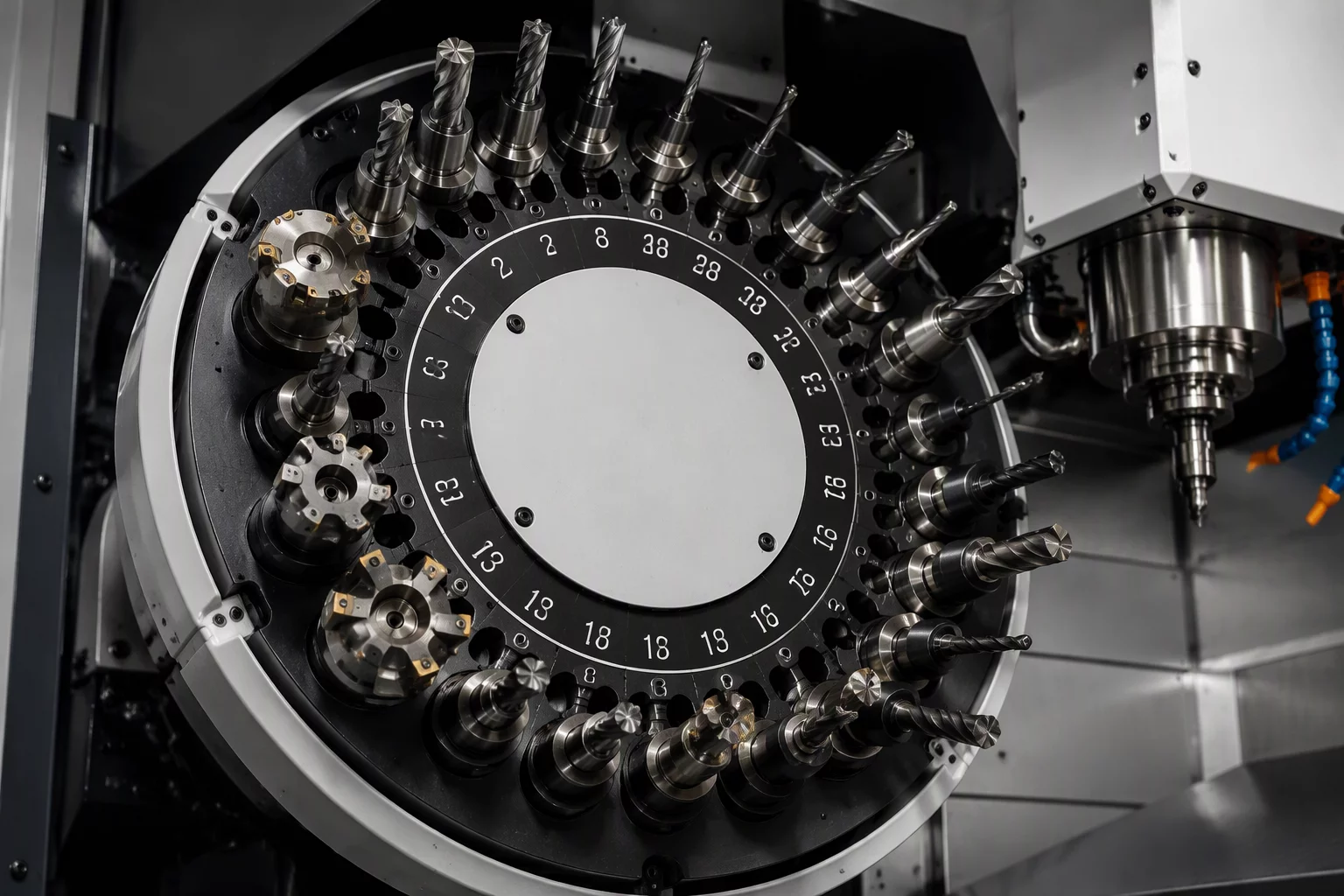
High precision CNC machine spindle performing programmed toolpath
Manufacturing IntelligenceCAM Field Notes

Document the Purpose Behind Each Machining Operation

Explore machining cases about feature access, roughing intent, finishing intent, remaining stock, and operation sequence.

Stock IntegrityVolumetric Residuals
Process RoutingDeterministic Flow
Clearance LogicZero Interference
Operational Framework

The Core Machining Architecture

Every toolpath sequence is governed by a singular technical inquiry: precisely defining what each stage accomplishes before subsequent cutting cycles commence.

Primary Planning Principle

What is this operation supposed to accomplish before the next one begins?

Failure to define clean stock targets, clearance conditions, and feature readiness creates compounded tool deflection, holder collisions, and dimensional drift down the sequence line.

Phase 01

Intent Cards

Declarative operation sheets pinpointing exact cycle mandates. Prevents aimless machining by binding each pass to explicit geometric boundaries.

  • Explicit cutting objectives defined
  • Non-negotiable safety corridors
Phase 02

Roughing Cases

High-velocity bulk material extraction strategies. Manages chip evacuation, steady flute contact, and structured volumetric load removal.

  • Constant radial engagement angles
  • Thermal transfer prevention
Phase 03

Finishing Cases

Final surface morphology, floor stepovers, and vertical wall integrity. Designed to satisfy drawing tolerances without deflection taper.

  • Wall taper deflection compensation
  • Micro-finish cusp heights
Phase 04

Feature Access

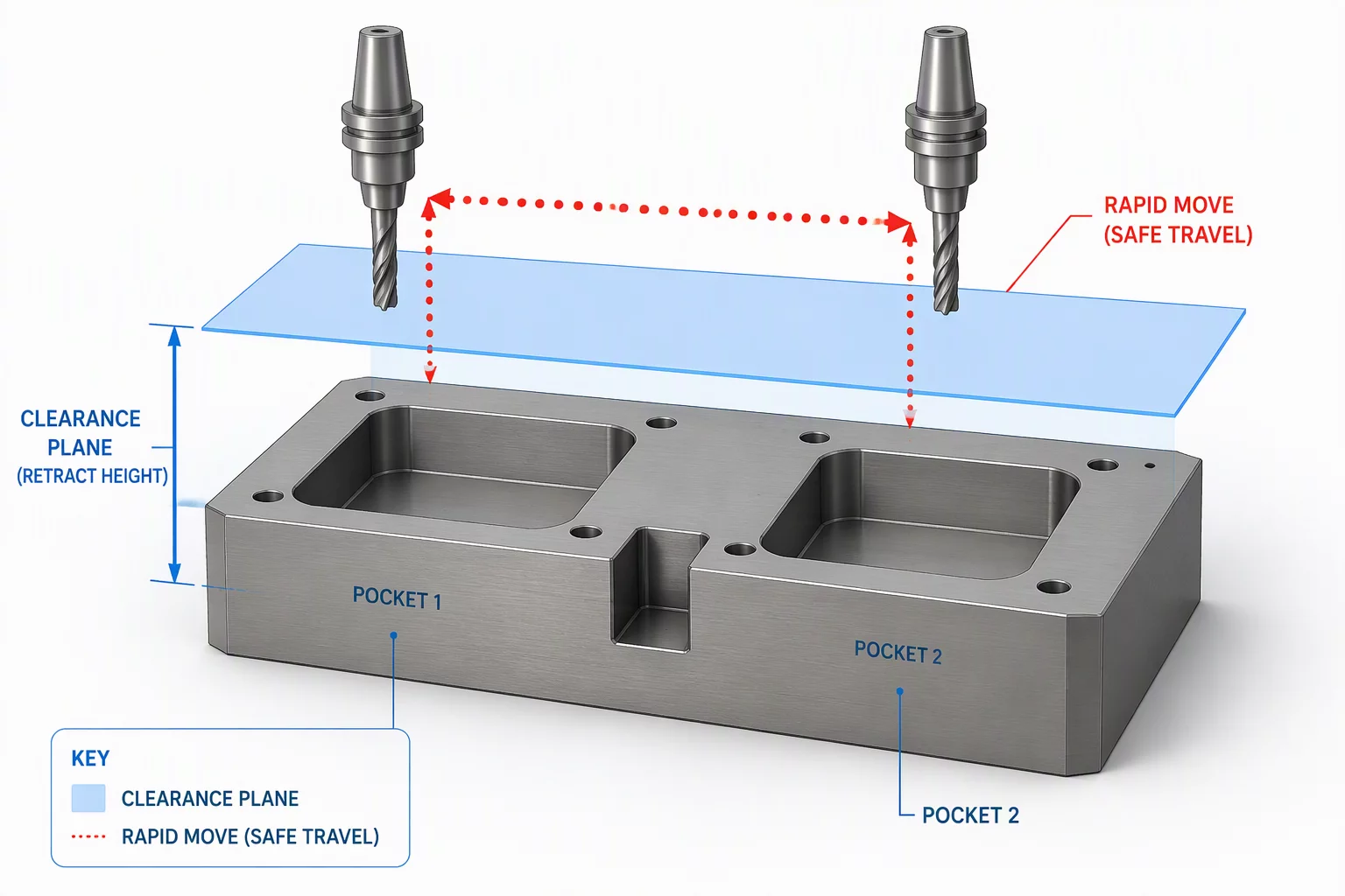
Collision envelopes, shank clearances, and multi-axis reach vectors. Guarantees safe toolholder entry into deep recesses and tight draft angles.

  • Multi-axis trunnion kinematic checks
  • Holder gouge & clearance planes
Phase 05

Remaining Stock

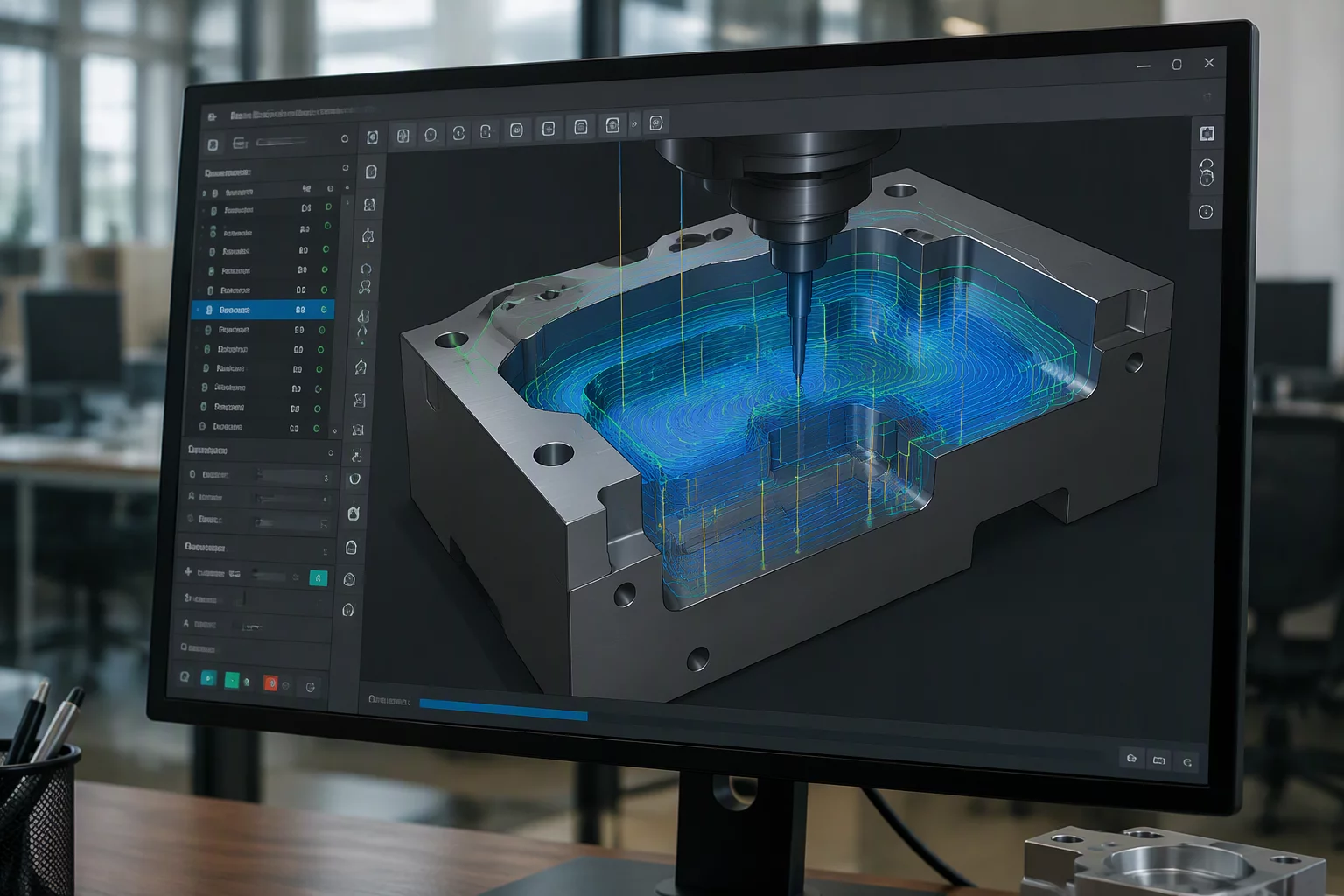
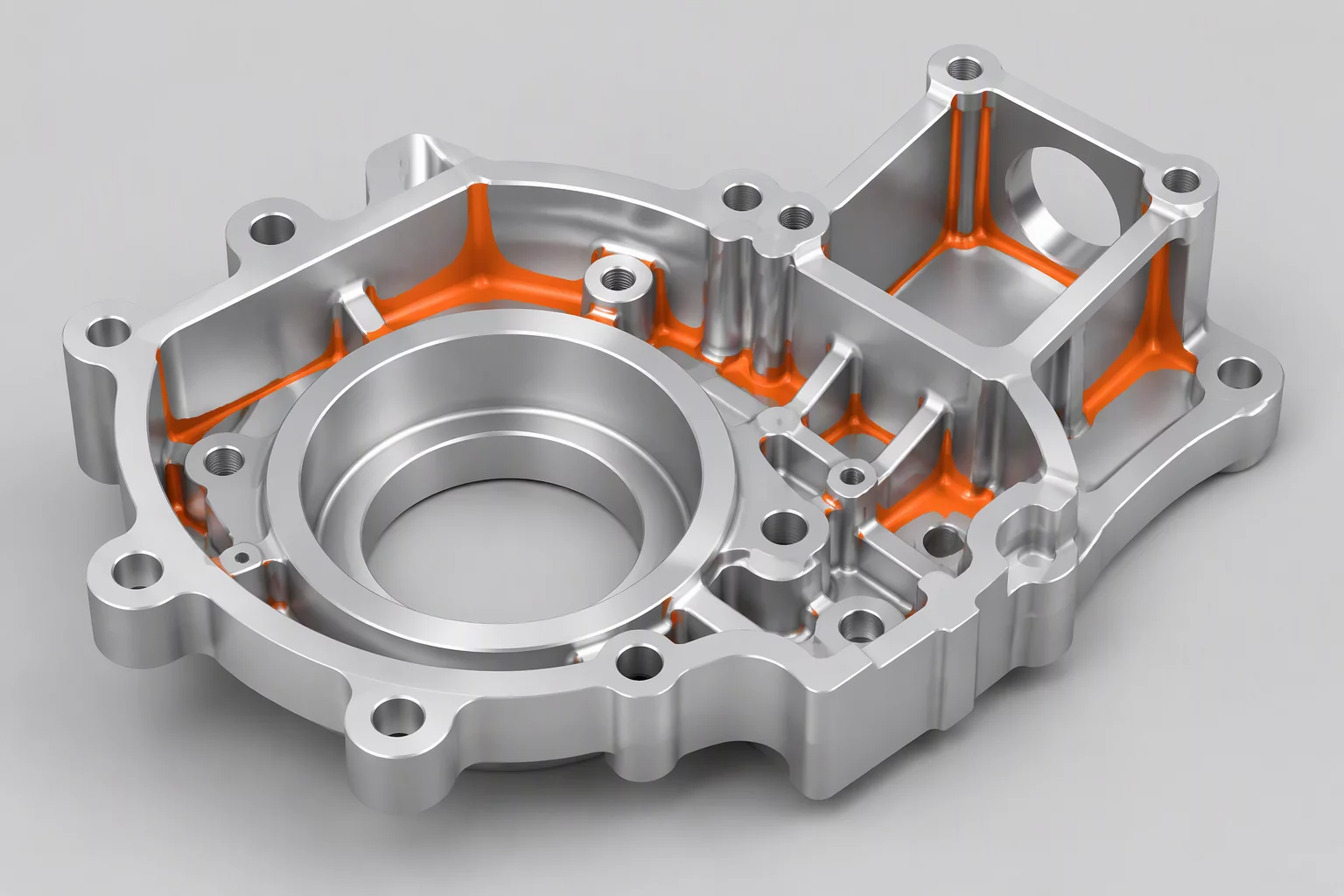
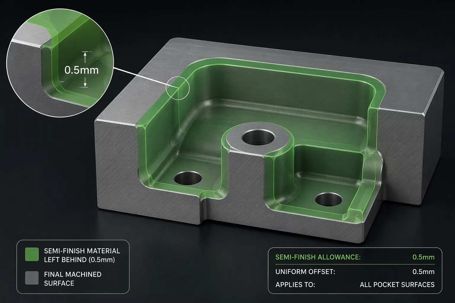
Accurate stock verification models tracking internal corner remnants. Sets uniform material envelopes for consistent semi-finishing loads.

  • Corner rest material evaluation
  • Semi-finish stock envelope stability
Phase 06

Operation Sequence

Strategic dependency mapping across operations. Minimizes tool carousel indexing while grouping identical operations to slash cycle times.

  • Tool carousel index optimization
  • Operation dependency locking
Execution Critical

Handoff Notes & Protocol

The direct communication conduit between CAM programmer and CNC machinist. Setup documentation must eliminate verbal ambiguity at the spindle.

Gauge Length Validation

Specifies exact holder projections, shrink-fit lengths, and minimum stickout limits to prevent chatter while guaranteeing bore accessibility.

Critical Datum Verification

Logs G54/G55 coordinate origins, soft jaw probing targets, and in-process caliper checkpoints prior to running irreversible finishing passes.

Documented directly within Mastercam setup sheets and machine program headers.
PROGRAMMING GUIDE

TECHNICAL WORKFLOW BRIEFS

FIELD-TESTED ROUGHING STRATEGIES

Engineered toolpath planning protocols focused on maintaining constant cutting loads, chip clearance, and geometric integrity prior to finishing.

Bulk Material Removal
ROUGHING • OCT 10, 2026

Bulk Material Removal

Learn how to clear large volumes of stock efficiently while managing thermal buildup and machine load distribution.

High Speed Roughing
ROUGHING • OCT 05, 2026

High Speed Roughing

Optimizing feed rates and stepovers for high speed passes without provoking chatter or accelerated cutter wear.

Core Roughing Logic
ROUGHING • SEP 28, 2026

Core Roughing Logic

Understanding primary volumetric engagement models and fundamental CAM decision criteria for complex pockets.

Rest Roughing Setup
ROUGHING • SEP 15, 2026

Rest Roughing Setup

Calibrating in-process stock tracking parameters to eliminate air cutting and isolate concentrated leftover stock.

Deterministic Process Pipeline

Roughing Complete — What Should Remain?

Transitioning from bulk excavation to finishing is where dimensional stability is either preserved or compromised. Explore the Mastercam workflow sequence that governs predictable residual stock.

Stage 01 • Geometric Definition

Deep Ribbed Cavity With Critical Wall Perpendicularity

A high-aspect structural pocket prone to tool deflection and thermal distortion. Initial raw billet measures 180mm x 120mm x 65mm in 7075-T6 aluminum. Dimensional tolerance specifies +0.010mm / -0.000mm with strict surface finish constraints.

7075-T6 Billet 4.5:1 Pocket Depth Zero Deflection Target
Stage Audit Metrics
Feature Depth:54.00 mm
Corner Radius:R4.00 mm
Target Ra:0.80 μm
Technical Deep Dives

Related Process Case Studies

Peer-reviewed CAM execution guidelines from Mastercam field engineers.
Remaining Stock • 2026-10-02 • Emily Zhang

Semi-Finish Material Targets

Establish exact geometric stock targets across high-speed dynamic cycles to prevent tool surge and protect carbide life.

Operation Sequence • 2026-10-06 • James Miller

Logical Progression Steps

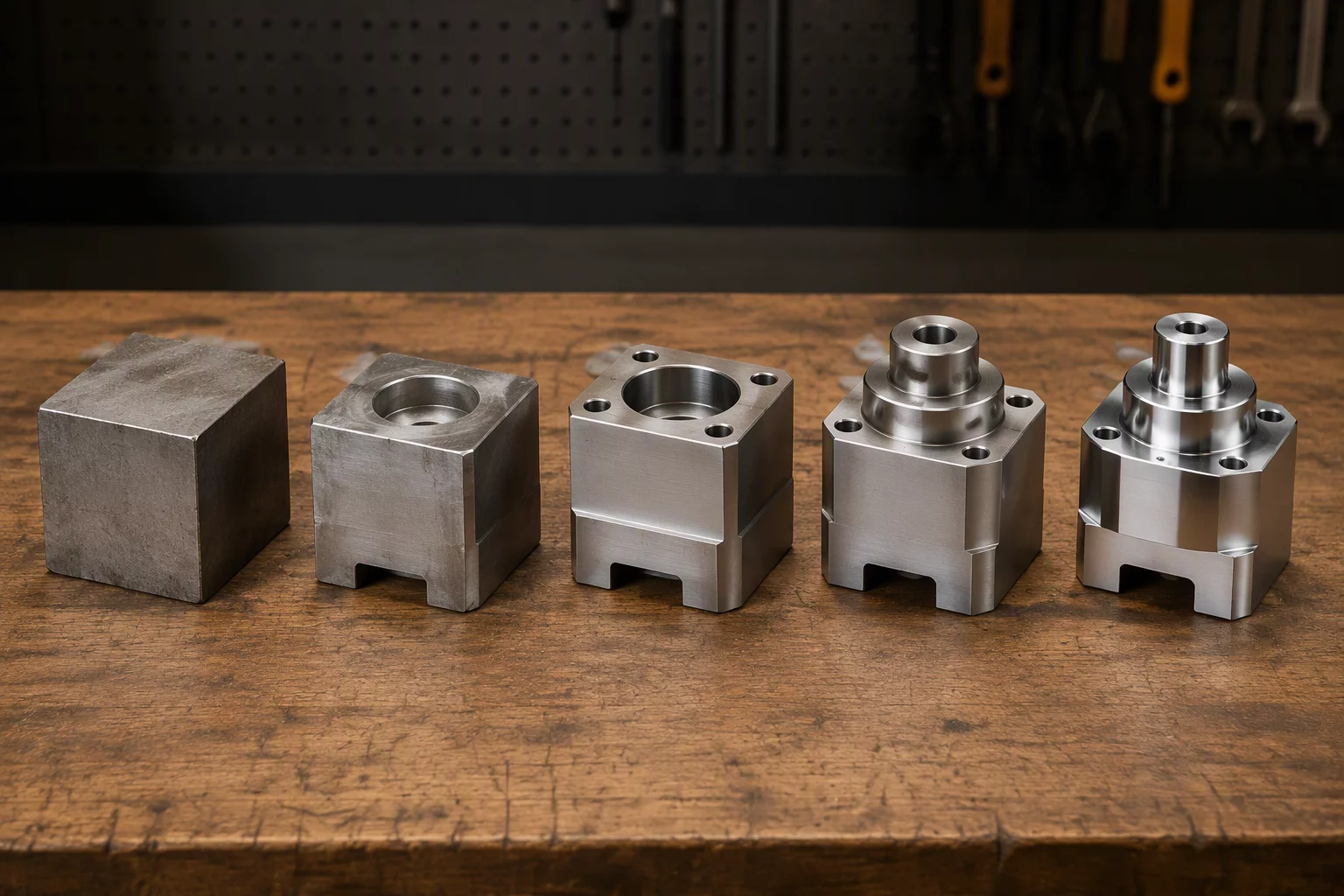
Architect disciplined step-by-step progressions from raw billet envelopes through to high-tolerance final feature verification.

PROJECT INITIATION CHECKLIST

MANDATORY CLIENT DECISIONS & ASSETS

Toolpath synthesis and cycle optimization cannot proceed without deterministic physical constraints. Review and supply all baseline engineering items below prior to operation planning.

TOTAL CRITERIA: 6 REQUISITES
ZERO-ASSUMPTION POLICY
MODEL DATAREQ #01

Frozen Solid CAD Geometry

Native Parasolid (.x_t) or STEP AP242 files with frozen revision tags. Surface normals must be verified, and all internal cavities modeled without wireframe ambiguity.

  • No unstitched surface bodies
  • Coordinate zero / part datum lock
MANDATORY STEP REVISED V2026.R2
BLUEPRINTREQ #02

Dimensioned GD&T Drawing

A fully dimensioned 2D PDF drawing detailing bilateral limits, true positions, thread class fits, and surface finish roughness thresholds (Ra/Rz) for critical planes.

  • Datum reference frame (A, B, C)
  • Designated sealing surface zones
QUALITY AUDIT APPROVED PDF
STOCK SPECSREQ #03

Material Grade & Form Factor

Precise alloy designation, heat treatment condition, and starting raw material dimensions (saw-cut extruded billet, continuous plate, or pre-formed casting).

  • Brinell/Rockwell hardness targets
  • Stock envelope allowance (+/- 3mm)
FEED SELECTION LOT TRACEABLE
KINEMATICSREQ #04

Target CNC Machine Envelope

Machine kinematics configuration, physical axis travel limits (X/Y/Z and A/B/C), spindle interface standard (CAT40, BT30, HSK-A63), and maximum spindle RPM.

  • Post-processor file match ID
  • Table weight & tilt boundaries
SAFETY LIMIT CNC KINEMATIC
FIXTURINGREQ #05

Workholding & Clamp Heights

CAD geometry of designated modular vises, custom soft jaws, vacuum chucks, or toe-clamp assemblies to define collision boundaries and tool clearance heights.

  • Max protruding clamp Z-height
  • Part overhang support constraints
ANTI-COLLISION BOUNDARY LOCK
TOOL CRIBREQ #06

Approved Tool Library & Gage Lengths

List of stocked end mills, indexable face cutters, drills, taps, shrink-fit holders, and permissible stick-out gage lengths to prevent tool chatter and premature wear.

  • Coating types (AlTiN, TiB2, DLC)
  • Max available carousel pockets
TOOL PATHING STOCKED ONLY
READY TO SUBMIT YOUR MACHINING PACKAGE?

Connect with our technical team to verify project documentation

We review model integrity, GD&T tolerances, and machine clearance profiles before initiating toolpath programming or G-code generation.

Core Technologies & Toolsets

Engineered Standards in CAM Operation Planning

Refining every Mastercam toolpath workflow and machining sequence with verified digital twins, deterministic strategies, and physical machine kinematics.

Kernel Engine

Mastercam 2026 / 2027 Ecosystem

Centralized computation platform providing algorithmic control over high-feed trochoidal passes, dynamic motion envelopes, and multi-surface boundaries.

Environment: 3-Axis & Multiaxis
Collision Safety

G-Code & Stock Verification

Synchronized collision detection checking real spindle housings, shank stepdowns, fixtures, and intermediate stock model remnants before cutting.

Tolerance: ±0.002 mm In-Process
Assembly Model

Digital Tool & Holder Libraries

Accurate solid definitions of shrink-fit holders, modular extensions, indexable inserts, and bullnose endmills for exact engagement angle planning.

Format: ISO 13399 Standard
Field Case Studies

Operational Studies in Toolpath Execution

Real-world examples proving how deliberate CAM operation planning and controlled machining sequence cut cycle overhead and spindle wear.

Managing Corner Remnants
Remaining Stock 2026-09-20 Michael Brown

Managing Corner Remnants

Handling corner material buildup safely through incremental rest milling and adaptive radii within the Mastercam toolpath workflow.

Minimizing Tool Changes
Operation Sequence 2026-09-25 Robert Cole

Minimizing Tool Changes

Sequencing to minimize ATC tool changes while maintaining feature datum integrity and an optimal machining sequence across setups.

Engagement Options

Structured Engineering Formats

Choose how we optimize your technical production. We specialize in robust CAM operation planning, fixture-aware strategies, and repeatable shop-floor cycle execution.

Single Engagement

Single Project

Focused end-to-end programming for a complex component, prototype setup, or critical production ramp-up.

  • Complete Mastercam toolpath workflow setup
  • Detailed stock model tracking & verification
  • Tooling bill of materials and digital setup sheet
  • Collision-free clearance and holder verification
  • Post-processed G-code verified for your machine
Advisory Session

One-Time Consultation

A targeted 90-minute technical deep dive to diagnose cycle bottlenecks, tooling vibration, or multi-axis access deadlocks.

  • Direct screen review of CAM operation planning
  • Tool selection and engagement angle audit
  • Rest-roughing parameters and feed stability check
  • Actionable technical summary checklist delivered
  • Follow-up question window via direct email
Inquire & Schedule

Book Your Engineering Session

Tell us about your machinery, materials, and current Mastercam toolpath workflow challenges to establish the right machining sequence before cutting metal.

Engagement Framework

Transparent Payment Protocols & Contract Terms

Clear terms governing CAM programming retainers, stage-gate deliverables, milestone disbursements, and dynamic machine-tool verification cycles.

Engineering Retainer

Initial Deposit Protocol

All dedicated CAM programming and process planning commissions require an initial 40% upfront engineering deposit before raw CAD ingestion and tool assembly modeling begin.

  • Secures dedicated post-processor engineer slot
  • Covers kinematically verified toolholder imports
Protected Escrow

Bank Escrow Allocation

For multi-axis production work packages exceeding ten distinct CNC setups, initial deposits may be deposited into an institutional escrow ledger payable upon rough stock verification.

  • Direct commercial wire routing
  • Mutual sign-off on first simulation run
Clear Invoicing

Itemized Billing Receipt

All retainers issue an automatic corporate tax invoice detailing assigned spindle kinematic sets, target controllers, and expected revision turnover timelines.

  • Net zero credit terms for deposit phase
  • Electronic fund transfers with swift receipts

Have a Custom Machine Programming Requirement?

Contact our technical department to receive an itemized proposal with explicit milestone staging tailored to your machine kinematic capabilities.

Publication Scope & Legal Boundaries

Educational Boundaries & Software Separation

ToolpathIntent Notebook is an autonomous engineering research and educational publication. We document machining strategies, geometric accessibility, and operation sequencing strictly for instructional purposes.

No Software Sales

Independent Publication & Licensing Notice

ToolpathIntent Notebook does NOT distribute, sell, license, or resell Mastercam® software, add-ons, or proprietary installation packages. Mastercam® is a registered trademark of CNC Software, LLC. We hold no commercial endorsement or distributor affiliation.

Scope Ref: SEC-01
No Machine Code

Zero Production NC Code Delivery

This publication never furnishes production-ready numerical control (NC) code, machine post-processors, or live controller G-code files. All illustrations, parameters, stepovers, and tool vectors are strictly conceptual representations intended for CAM workflow comprehension.

Scope Ref: SEC-02
Verified Timeline

Version Release Chronology & Context

Historical technical comparisons and release notes reference public milestones: Mastercam 2026.R2 launched on February 9, 2026, and Mastercam 2027 debuted on July 1, 2026. These references ensure historical accuracy for machining engineers evaluating legacy and modern CAM workflows.

Scope Ref: SEC-03

Shop Floor Verification Protocol

CNC programmers and machine operators are solely responsible for testing offsets, verifying simulated clearance planes, checking fixture geometry, and validating safe feeds on physical machine tools before cycle start.

Official Disclaimer

Independent Educational Resource

ToolpathIntent Notebook is an independent educational resource and is not affiliated with or endorsed by Mastercam. Mastercam is referenced for informational purposes only. All registered trademarks, trade names, and software brands belong exclusively to their respective owners.